Search



WORLDWIDE SHIPPING
fast, flexible, secure options

ONLINE SUPPORT 24 / 7
anytime, anywhere help

MONEY BACK GUARANTEE
shop with confidence

WIDE SELECTION
every day low prices
DIY Parts & Components
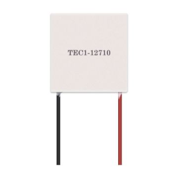
TEC1-12710 Thermoelectric Cooler Peltier Element Module
- Number of component pairs: 127
- Assembly pressure: 85N/cm2
- Be sure to apply thermal grease when installing the radiator
- The literal is cold side, and the non-literal is hot side
- Packaging process: standard 704 silicone rubber seal around
- Packaging standard: foam box packaging, storage conditions ambient temperature -10 ~ 40 degrees Celsius
- Working environment: temperature range -5583 degrees Celsius (excessive ambient temperature will directly affect the cooling efficiency)
- The working state of the cooling plate is that one side is cooling and the other side is heating, and the heating surface must be well dissipated during work. It is strictly forbidden to energize for more than 2 seconds without heat dissipation, so as to avoid overheating and burning.
A$12.82 A$14.74
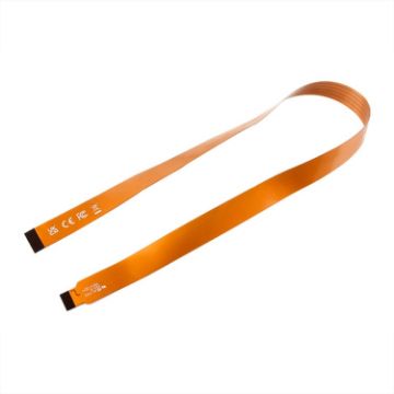
Waveshare 25947 For Raspberry Pi 5th DSI Display 22Pin To 15Pin Soft Cable FPC Cable, Spec: 500mm
- For Raspberry Pi 5 to connect DSI display
- 22Pin to 15Pin
- 200 / 300 / 500mm optional
- Made of high-quality material, flexible and durable
- The picture is for display only, DSI cable and CSI cable cannot be mixed
- Note: Only DSI cable will be shipped, no other!
A$16.66 A$20.16
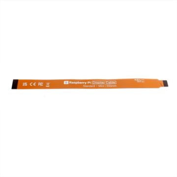
Waveshare 25947 For Raspberry Pi 5th DSI Display 22Pin To 15Pin Soft Cable FPC Cable, Spec: 200mm
- For Raspberry Pi 5 to connect DSI display
- 22Pin to 15Pin
- 200 / 300 / 500mm optional
- Made of high-quality material, flexible and durable
- The picture is for display only, DSI cable and CSI cable cannot be mixed
- Note: Only DSI cable will be shipped, no other!
A$9.60 A$11.33
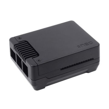
Waveshare 26587 For Raspberry Pi 5 Argon Neo Aluminum Alloy Case, Spec: M.2 Upgraded
- For Raspberry Pi 5th generation
- Made of aluminum alloy, high hardness and strong pressure resistance
- The shell has reserved GPIO slots and various interfaces
- Built-in 30mm PWM fan, good heat dissipation effect
- Equipped with anti-skid pad and power button
- Simple installation and convenient operation
- Product size: Standard version: 95.5 x 71.5 x 30mm, upgraded version: 95.2 x 71.4 x 40mm
- Note: The delivery does not include Raspberry Pi 5 motherboard and M.2 hard drive!
A$97.33 A$118.73
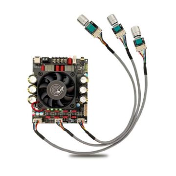
HIFI Dual-Channel High-Power TPA3255 Digital Amplifier Board (Split Type)
- Bluetooth chip: Jie Li 5.3, transmission distance 10 meters
- Input method: Bluetooth + AUX + U disk / sound card
- Number of channels: 2.0, left channel + right channel
- Amplifier chip: original TPA3255
- Protection mechanism: input undervoltage, overheating, overcurrent, short circuit protection, no input reverse connection protection, positive and negative poles cannot be reversed!
- Adapter power supply: working voltage range 18-50VDC, limit 53V, recommended voltage 36-48V, current 10A or more DC power supply
- Power: single channel 300w@50V, 4 ohms; 160W@50V, 8 ohms; the higher the voltage, the smaller the resistance, the greater the output power
- Size: 118x100x38mm
A$53.91 A$64.16
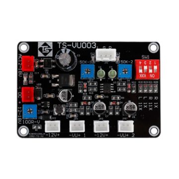
VU Meter Driver Board Module Adjusts Power Amplifier (TS-VU003)
- AC/DC12-16V power supply, distinguish between AC and DC input terminals. L, G, R: These are the dual-channel input terminals of the driver board, which can be connected to the audio of mobile phones, computer sound cards, preamplifiers and other audio source devices (the signal is the signal that the headphones can hear), and the amplifier output terminal to get the signal. When wiring, L, G, and R correspond to the left, ground, and right channels of the audio source device respectively. If the input is a mobile phone, computer sound card, preamplifier and other audio sources, please turn the dip switches 1 and 3 to the ON end. 1. AC/DC12-16V power supply, distinguish between AC and DC input terminals
- L, G, R: This is the dual-channel input terminal of the driver board, which can be connected to the audio of mobile phones, computer sound cards, preamplifiers and other audio source devices (the signal is the signal that can be heard by headphones), and the output of the power amplifier. When wiring, L, G, and R correspond to the left, ground, and right channels of the audio source device respectively. If the input is a mobile phone, computer sound card, preamplifier and other audio sources, please turn the dip switches 1 and 3 to the "ON" end. If the input is the output of the power amplifier, please turn the dip switches 2 and 4 to the "ON" end. The signal will be compressed 11 times. Note that the dip switches 1 to 4 cannot be turned to the "ON" end at the same time.
- The adjustable potentiometer "100R-V" is used to adjust the brightness of the vu meter backlight
- The adjustable potentiometers "50k-1" and "50k-2" control the pointer jump amplitude of VU meter 1 and VU meter 2 respectively
- Made of high-quality glass fiber ABS material
- The driver board components are finely manufactured and durable
- Stable performance makes the VU meter better, the pointer swings quickly, the response is sensitive, the wide range voltage stabilization circuit, and the working performance is more stable
- This driver board supports low access, has adjustable brightness and darkness backlight, and intelligent drive
A$16.97 A$19.69
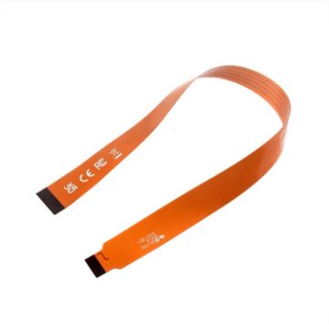
Waveshare 25947 For Raspberry Pi 5th DSI Display 22Pin To 15Pin Soft Cable FPC Cable, Spec: 300mm
- For Raspberry Pi 5 to connect DSI display
- 22Pin to 15Pin
- 200 / 300 / 500mm optional
- Made of high-quality material, flexible and durable
- The picture is for display only, DSI cable and CSI cable cannot be mixed
- Note: Only DSI cable will be shipped, no other!
A$9.60 A$11.61
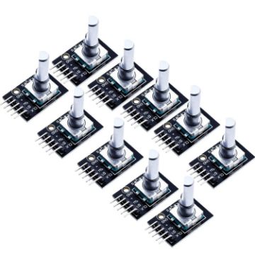
10 PCS KY-040 360 Degree Rotary Encoder Module
- Material: Electronic components + PCB
- Working voltage: 5V
- Number of pulses per revolution: 20
- The rotary encoder can count the number of output pulses during rotation in the forward and reverse directions by rotation. Unlike the potentiometer, the rotation count is unlimited. With the buttons on the rotary encoder, it can be reset to the initial state, that is, counting from 0.
- Working principle: The incremental encoder is a rotary sensor that converts the rotational displacement into a series of digital pulse signals. These pulses are used to control angular displacement. The conversion of angular displacement in the Eltra encoder uses the photoelectric scanning principle. The reading system is based on the rotation of the radial index disc (code disc) composed of alternating light-transmitting windows and opaque windows, and is simultaneously illuminated vertically by an infrared light source, and the light projects the image of the code disc onto the surface of the receiver . The receiver is covered with a layer of diffraction grating, which has the same window width as the code wheel. The receiver's job is to feel the changes produced by the rotation of the disc, and then convert the light changes into corresponding electrical changes. Then the low-level signal is raised to a higher level, and a square pulse without any interference is generated, which must be handled by an electronic circuit. The reading system usually uses a differential method, that is, comparing two different signals with the same waveform but a phase difference of 180 in order to improve the quality and stability of the output signal. The reading is formed based on the difference between the two signals, thereby eliminating interference.
A$14.77 A$17.72
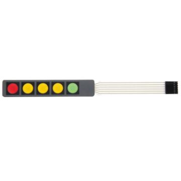
10 PCS Matrix 1 x 5 Keys Membrane Switch Keypad
- Made of quality material, durable to use.
- 6 pins pitch connector, 1x5 type 5 keys.
- White sticker can peel off for adhesive mounting.
- The back can be firmly fixed to the chassis surface.
- Used widely in industrial and home electronic equipments, instrument, etc.
A$18.94 A$21.96
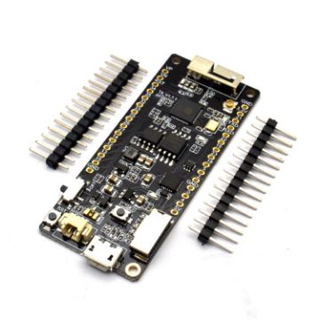
TTGO T8 V1.7 WiFi Bluetooth Module ESP32 WROVER 4MB FLASH 8MB PSRAM Module
- Espressif official ESP32-WROVER module
- New ESP32 version: REV1
- Wireless Internet
- Bluetooth
- 4MB flash memory
- 8MB PSRAM
- Lithium battery interface, 500mA maximum charging current
- Support TF memory card
A$25.62 A$29.72
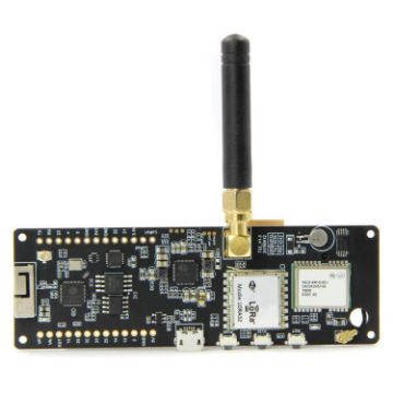
TTGO T-Beamv1.0 ESP32 Chipset Bluetooth WiFi Module 433MHz LoRa NEO-6M GPS Module with SMA Antenna, Original Version
- Working voltage: 1.8~13.7V
- Acceptable current: 10~114mA
- Emission current:
- 120mA at + 20dBm
- 90 mA lies at +17dBm
- 29mA at +13dBm
- Working frequency: 923MHz
- Transmitting power: + 20dBm
A$68.07 A$83.04
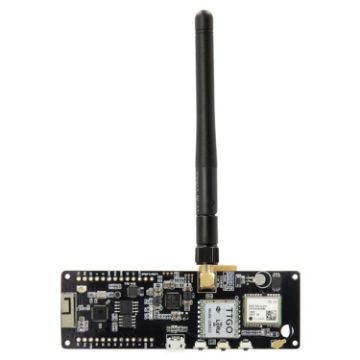
TTGO T-Beamv1.0 ESP32 Chipset Bluetooth WiFi Module 915MHz LoRa NEO-6M GPS Module with SMA Antenna, Original Version
- Working voltage: 1.8~13.7V
- Acceptable current: 10~114mA
- Emission current:
- 120mA at + 20dBm
- 90 mA lies at +17dBm
- 29mA at +13dBm
- Working frequency: 923MHz
- Transmitting power: + 20dBm
A$64.88 A$75.26

NEED HELP?
Payment options
